E24 : Pressure Imbalance

To avoid serious injury follow all warnings and instructions in the manual. Wear appropriate personal protective equipment.
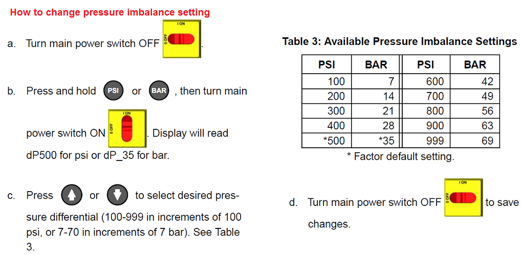
There is a pressure imbalance between the “A” and “B” fluids that is higher than allowed by the motor control board. Available control settings are between 100 – 999 psi, or 7 – 35 bar. See table below.
There can be two types of E24 errors, depending on whether the pressure gauges are approximately equal, or not equal.
The digital display on a Reactor always shows the higher of the two pressures. As soon as the higher analog pressure drops below the lower analog pressure the digital display will switch to the new highest reading. Knowing this, the following tests should show which pressure transducer has failed.
- For testing purposes only – Find the dip switches (labeled SW2 in the manual) on the motor control board, and set dipswitch 3 to off on E-Series Reactors. This will allow the Reactor to run with a pressure imbalance warning.
- Run the unit to build up pressure (1000 – 1200 psi) with the motor ON key. When the machine then stalls at set pressure, press the motor OFF key to clear the E24 warning, but don’t depressurize the unit.
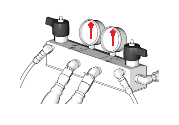
- Check the analog gauges to see which pressure is higher. And then check and see if the pump display pressure matches. If it does, that would indicate that the motor control board is “Seeing” that transducer.
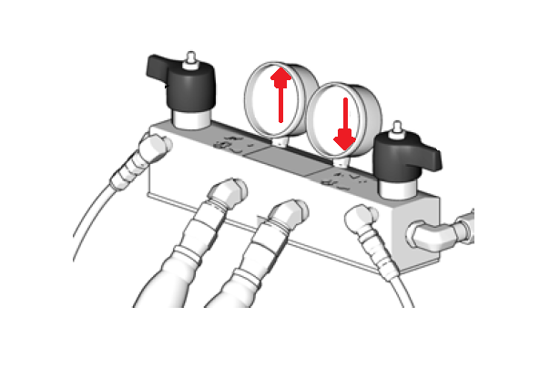
- With the pump still off, use the pressure relief/spray valve to slowly relieve the “higher” side pressure, while watching the digital display and the analog gauges. Once the higher analog gauge drops below the lower analog pressure the pump display should start reading the “new” higher side pressure (because it is now the higher of the two). Then slowly drop the “new” higher side pressure until the digital display stops at the original “higher” side analog gauge reading.
- The last test is to determine if the pressure transducer has failed or if the socket on the pressure control board has gone bad.
- Swap the transducer plug-ins on the motor control board. (J3 & J8 for the E-20 & E-XP1 and H series Reactors. J3 & J5 for the E-30 & E-XP2)
- Repeat above test.
- If the problem stays with the same side as before then the pressure transducer is bad.
- If the problem appears to switch over to the other transducer, then the problem is in the motor control board socket.
- Adjust Pressure Imbalance setting. Adjust to a higher setting to reduce random nuisance errors
- Try clearing the error and balancing the pressures using the dump valves.
If we can determine what chemical “A” or “B” is coming out of the gun, then we can focus on the missing chemical side. This will immediately save us time by checking the side that is lacking chemical or is the cause of our problem.
First we need to understand that the restriction of the mix chamber impingement port sizing creates the backpressure that we monitor at the fluid outlet gauges. Think of it as holding your thumb over the end of the garden hose. The more we block, or “restrict” the opening, the greater the backpressure we create.
Restrictions can include,
- blockage in the mix chamber,
- gun screen,
- whip hose,
- hose temperature sensor,
- main fluid line,
- manifold outlet.
“A” side chemical is thicker than the “B” due to cold material or primary heater problem.
“B” side mix chamber port has been increased by wear, reducing the “B” side back pressure causing a resin rich, or too much “B” condition.
Starving the supply with one of the following:
- Supply feed pump malfunction,
- Restriction of the feed hose or filter strainer,
- Drum is not properly vented due to bung cap in place or desiccant breather clogged.
- Debris in the bottom of the drum container,
- Dented drum bottom restricting the feed pump inlet,
- “A” side proportioner pump has debris or a stuck ball in the inlet or discharge ball check seat area.
- If circulating material back to the drum, the pressure relief/spray valve could be leaking, or diverting pressure and material back to the drum.
- Restrictions that can include,
- blockage in the, mix chamber,
- gun screen,
- whip hose,
- hose temperature sensor,
- main fluid line,
- manifold outlet
- “B” side chemical is thicker than the “A” due to cold material or primary heater problem.
- “A” side port has been increased by wear, reducing the “A” side back pressure causing an ISO rich, or too much “A” condition.
Starving the supply with one of the following:
- Supply feed pump malfunction,
- Restriction of the feed hose or filter strainer,
- Drum is not properly vented due to bung cap in place or desiccant breather clogged.
- Dented drum bottom restricting the feed pump inlet,
- “A” side proportioner pump has debris or a stuck ball in the inlet or discharge ball check seat area.
- If circulating material back to the drum, the pressure relief/spray valve could be leaking, or diverting pressure and material back to the drum.