Maintenance Schedule

To avoid serious injury follow all warnings and instructions in the manual. Wear appropriate personal protective equipment.
The operating conditions of your particular system determine how often maintenance is required. Establish a preventive maintenance schedule by recording when and what kind of maintenance is needed, and then determine a regular schedule for checking your system.
Disassemble and clean the pump at the end of every day. The procedure takes about 10 minutes. As items are disassembled, use a soft brush and water or a compatible solvent to clean components.
- Flush the system. See Flush, in manual. Stop pump near bottom of its stroke.
- Perform Pressure Relief Procedure. See Pressure Relief Procedure, in manual.
- With fluid pressure relieved, remove material hose from pump outlet.
- Disconnect hopper at outlet camlock then remove hopper.
- Remove inlet elbow.
- Tip cart back so it rests on the back of the cart.
- While holding onto the inlet housing, use a 5/8 in. wrench to loosen the two nuts on the inlet housing clamp then remove inlet housing.
- Remove inlet ball stop and ball cage spring.
- Use 5/8 in. wrench to loosen the two nuts on the cylinder clamp then remove cylinder.
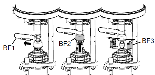
- Disconnect pump rod (see the following figure):
- Push piston rod protective spring up and away from coupling assembly (BF1-BF3).
- Remove clip (BF1), and slide coupling cover (BF2) up to remove coupling (BF3).
- Pull rod down and out of outlet housing.
- Remove outlet ball stop from rod by pushing o-rings off of ball stop.
- Loosen and remove packing nut then remove throat packing.
- Use a brush and solvent to clean all loose pieces.
NOTE: The pump rod is not disassembled unless the piston packing or seat needs to be replaced.
NOTE: The inlet housing is not disassembled unless the inlet seat needs to be replaced.
- Loosely install throat packing with the open end facing into the pump.
- Install packing nut hand-tight.
- Lubricate the balls to ensure they do not stick.
- Install outlet ball, outlet ball stop with o-rings into rod. Ensure outlet ball stop o-rings are in the grooves on the outlet ball stop rod.
- Grease the packing on the rod.
- Gently slide rod through throat packing.
- Install coupling (BF3), slide coupling cover (BF2) over coupling, then install clip (BF1) to secure pump rod to air motor.
- Use a flat-tip screwdriver and a plastic mallet to tighten packing nut until it stops.
- NOTE: This is not an adjustable packing but the packing nut does need to be tight against the throat packing.
- Slide cylinder over rod with o-ring installed between outlet housing and cylinder.
- NOTE: If the o-ring does not stay in place while assembling the cylinder to the housing, the cart may need to be tipped upright to install properly. After clamp is installed, tip cart back to horizontal position to finish assembly.
- Use cylinder clamp to secure cylinder to outlet housing.
- NOTE: Each clamp has one flat so that only one wrench is required to tighten clamp. Align bolt head with flat then use a wrench on the nut to tighten. Tighten both sides of the clamp evenly to approximately 10 ft-lb (14 N•m).
- Install inlet ball, ball cage spring, and inlet ball stop in inlet housing.
- With inlet ball, ball cage spring, and inlet ball stop in place, place o-ring between cylinder and inlet housing then use inlet housing clamp to install inlet housing onto cylinder.
- NOTE: Each clamp has one flat so that only one wrench is required to tighten clamp. Align bolt head with flat then use a wrench on the nut to tighten. Tighten both sides of the clamp evenly to approximately 10 ft-lb (14 N•m).
- Install inlet elbow onto inlet housing.
- Tip cart up.
- Install hopper onto the hopper bracket and connect to inlet elbow.
- Install material hose onto pump outlet.
- 17. Wrap blue, velcro, camlock retaining straps around each camlock connection to secure.
- NOTE: This includes the two camlocks between the hopper and pump lower, the camlock at the pump outlet, the camlocks on the fluid hoses, and the camlock on the applicator inlet. The retaining straps should be tight and must not be able to slide off camlock.
- Add TSL to the packing nut until 1/2 full.
- Flush the system. See Flush, in manual.
- Relieve pressure. See Pressure Relief Procedure, in manual.
- Perform the Disassemble and Clean the Pump procedure at the end of every day.
- Drain water from air filter.
- Clean hopper with a scrub pad. It is recommended that you clean the outside of the sprayer using a cloth and compatible solvent.
- Check hoses, tubes, and couplings. Tighten all fluid connections before each use.
- Check and replace camlock gaskets as needed.
- To prevent rust, never leave water or water-based fluid in the pump overnight.
- Material left on the throat seal can dry out and damage the seal.
- Always stop the pump at the bottom of the stroke to avoid damage to the throat seal.
- Always flush the pump before the fluid dries on the displacement rod.
- First, flush with water, then with oil.
- Relieve the pressure, but leave the oil in the pump to protect the parts from corrosion.
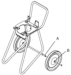
- Periodically lubricate the axle between points A and B with lightweight oil. See the following figure.
- Keep the cart clean by wiping up spills daily, using a compatible solvent.