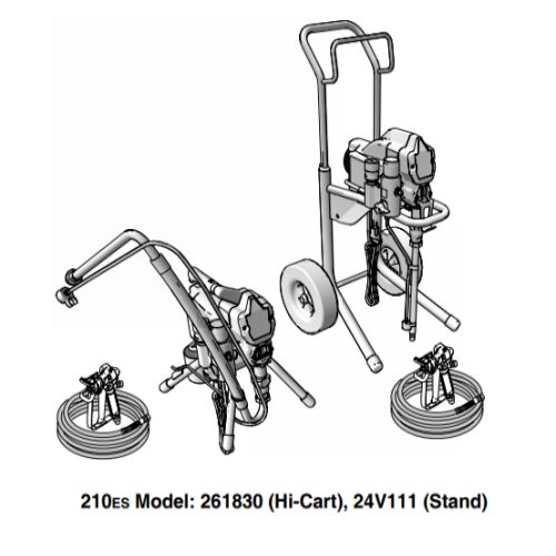
Magnum Pro 210es - 261830/24V111

To avoid serious injury follow all warnings and instructions in the manual. Wear appropriate personal protective equipment.
Sprayer is Not Priming
Clearing a Tip Clog
Basic Trouble Shooting
Is the sprayer turning on?
Is it priming?
Does it spray at all?
There are several causes:
1. The needle is held open with debris.
2. The grey nut at the back of the gun is turned too tight, loosen it slightly.
3. The needle may be worn and needs to be replaced. Have the gun serviced or install a new repair kit for the specific gun you are using.
Is it a new sprayer?
Jog the motor.
Did this resolve the issue?
The issue is resolved.
Powerflush the sprayer.
Did this resolve the issue?
Have you already been spraying today?
Check the following:
- Turn up the pressure control knob.
- Plug directly into a non-GFCI outlet.
- Check for a burnt fuse (ProX models only).
Did this resolve the issue?
Reverse the spray tip and try to clear a tip clog.
Did this resolve the issue?
The issue is resolved.
Check the following:
- If you sprayed a lot today allow motor to cool for 30 minutes and try again.
- Verify extension cord is at least 14 gauge and no longer than 50 ft.
- Turn up the pressure control knob.
- Plug directly into a non-GFCI outlet.
- Check for a burnt fuse (ProX models only).
Did this resolve the issue?
Follow these steps:
- Make sure the suction tube (the larger, braided tube) and the strainer are completely submerged in the paint.
- Some paints are very thick and require the pump to slow down to prime. Turn the on/off switch ON and then OFF until the pump is about to stops and then turn the sprayer ON and then OFF again. You may need to do this a few times until paint works its way into the pump and out the drain tube (smaller clear tube).
- Remove the suction tube (larger, braided tube). Insert the pointed end of a pencil into the inlet and push up to free the inlet valve ball.
- Remove and clean the outlet valve. (See component identification and troubleshooting in your owner’s manual.)
- Remove and clean the inlet valve. (See component identification and troubleshooting in your owner’s manual.) Be sure not to lose the inlet ball (some models have a spring as well).
- Remove the strainer and connect the Power Flush adapter and a garden hose to the suction tube. Following the directions in your owner’s manual, flush the sprayer with water for one minute. Reinstall the strainer on the suction tube, submerge the suction tube in the paint and prime the sprayer.
Make sure the unit is plugged into a working outlet. If it is, turn the sprayer on and then turn the sprayer’s pressure control knob clockwise until the motor starts running.
When the gun trigger is released, the motor and pump will automatically turn off. Once you pull the gun trigger and start spraying, the motor and pump will turn on again. This is normal operation and eliminates constant motor noise and reduces wear for longer life.
If the motor continues to run when the gun trigger is released, it is not primed.
Make sure the Prime/Spray Valve is pointed forward in the Spray position
The spray tip is likely clogged. Turn the spray tip 180 degrees to the unclog position, aim the spray gun into a bucket and pull the trigger for one second to clear the clog. Turn the spray tip back to the spray position and resume spraying.
The best way to reduce tip clogs is to strain you paint of the larger debris.
Make sure the pressure control is turned up to a higher spray pressure. Try moving closer to the surface. If you continue to see lines in your pattern, you may need a larger tip size if you sprayer can support it (the largest tip that the Project Painter Plus and X5/LTS15 can support is the tip that is included). Otherwise, add a small amount of water or solvent, depending upon your material. Be sure to work the water or solvent into the paint that is in your paint hose by reversing the tip and spraying the paint back into the paint bucket until the thinner material is worked into the paint hose. Don’t forget to turn your spray tip back to the spray position.
You most likely have a tip plug. Turn the spray tip 180 degrees to the unclog position, aim the spray gun into a bucket and pull the trigger for one second to clear the clog. Turn the spray tip back to the spray position and resume spraying.
The pump needs to be serviced or replaced.
The spray hose connection is not tight. Use a wrench to tighten the spray hose to the sprayer and to the gun.
Slowly increase pressure setting to see if motor starts.
Relieve pressure, page 6. Then clear clog or clean gun filter. Refer to gun instruction manual, 311979.
Thaw sprayer if water or water-based paint has frozen in sprayer. Place sprayer in warm area to thaw. Do not start sprayer until thawed completely. If paint hardened (dried) in sprayer, replace pump packings. See page 12, Displacement Pump Replacement.
Push pin into place and secure with spring retainer. See page 12, Displacement Pump Replacement.
Replace motor if fan won’t turn. See page 27, Motor Replacement.
Turn ON/OFF switch to ON position. Reset building circuit breaker, replace building fuses. Try another outlet.
Replace extension cord.
Replace power supply cord. See page 26, Power Cord Replacement.
Replace fuse after completing motor inspection. See page 21, Fuse Replacement.
Replace loose terminals; crimp to leads. Be sure terminals are firmly connected. Clean circuit board terminals. Securely reconnect leads.
Replace motor. See page 27, Motor Replacement.
Install brush cap or replace brushes if leads are damaged. See page 17, Motor Brush Replacement.
NOTE: Brushes do not wear at the same rate on both sides of motor. Check both brushes. Replace brushes. See page 17, Motor Brush Replacement.
Remove motor and have motor shop resurface commutator if possible. See page 27, Motor Replacement.
Replace motor. See page 27, Motor Replacement.
Insert pressure control connector into control board.
Relieve pressure, page 6. Replace tip. Refer to gun instruction manual, 311979.
Service pump. See page 12, Displacement Pump Replacement.
Relieve pressure, page 6. Then repair prime valve. See page 24, Manifold Replacement.
Tighten any loose connections. Check o-ring on suction tube.
Reset building circuit breaker; replace building fuse. Repair electrical outlet or try another outlet.
Replace with a correct, grounded extension cord. See page 5, Grounding and Electric Requirements.
Be sure male terminal pins are centered and firmly connected to female terminals. Replace any loose terminals or damaged wiring. Securely reconnect terminals.
Replace brushes. See page 17. Motor Brush Replacement.
Clean brush holders. Remove carbon dust by using compressed air to blow out brush dust.
Replace pressure control assembly. See page 22, Pressure Control Assembly Replacement.
Replace motor. See page 27, Motor Replacement.
Close prime valve.
Refill and reprime pump
Remove and clean, then reinstall.
Tighten nut. Check o-ring on tube
See Pump Manual 312015. Strain paint before using to remove particles that could clog pump.
See Pump Manual 312015.
See Pump Manual 312015.
Replace pump pin if missing. Be sure retaining spring is fully in groove all around connecting rod. See page 12, Displacement Pump Replacement.
Replace connecting rod assembly. See page 12, Displacement Pump Replacement.
Inspect drive housing assembly and gears for damage and replace if necessary. See page 14, Drive Housing Replacement.
Move sprayer to shaded, cooler area if possible.
Replace motor. See page 27, Motor Replacement.
Loosen packing nut. Check for leaking around throat. Replace pump packings if necessary. See pump manual 312015.