E31 : Motor Drive Error

To avoid serious injury follow all warnings and instructions in the manual. Wear appropriate personal protective equipment.
- The motor control board has malfunctioned, “shorted” and needs to be replaced. Rarely is the control board the cause of this error. Other circumstances such as a motor failure or inadequate input supply voltage lead to this type of motor board failure. Not in all cases will an E31 error code appear.
- Another symptom of a motor drive failure is that the motor will immediately turn on when input power is applied to the Reactor, running away with no motor control. This is due to the control being shorted sending full voltage to the motor.
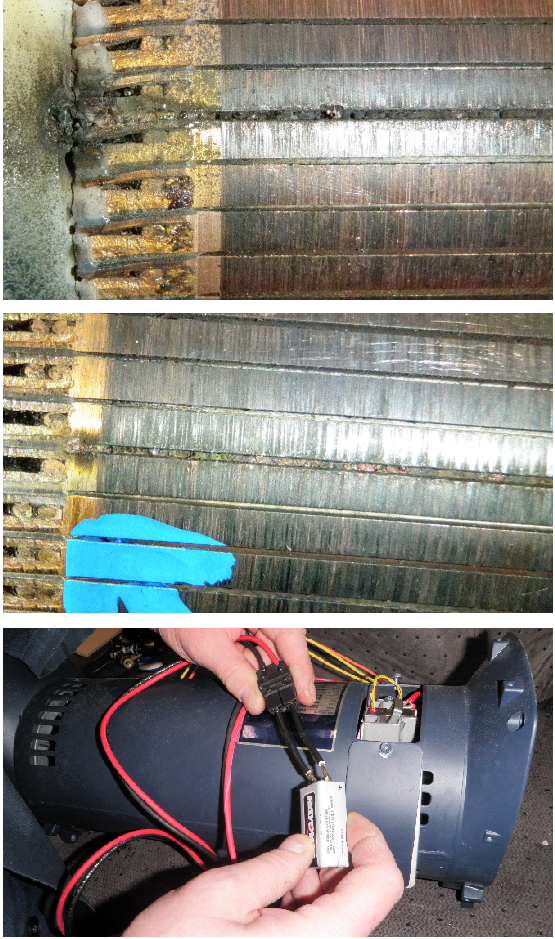
- After removing machine from the power source, the drive motor will have to be thoroughly check, by pulling the top motor brush and rotating the motor manually with the internal fan blade to inspect the motor commutator all the way around for any evidence of burning or pocking. Continue to rotate the motor until we have completed one pump cycle, up and down to insure there is no mechanical interference in pump lower, or gear drive system. Confirming rotation when connected to a 9vdc battery can then verify the motor is functioning properly. The Reactor machines that have the large Blue capacitor (E-30/E-XP2) will have to have it verified for proper function as well.
- If after confirming a good motor and capacitor, and confirming the input power source is at the required voltage and phase. Replace the drive board. Keep in mind that the power source should not be interrupted prior to powering down the Reactor unit. This would include the generator source running out of fuel.
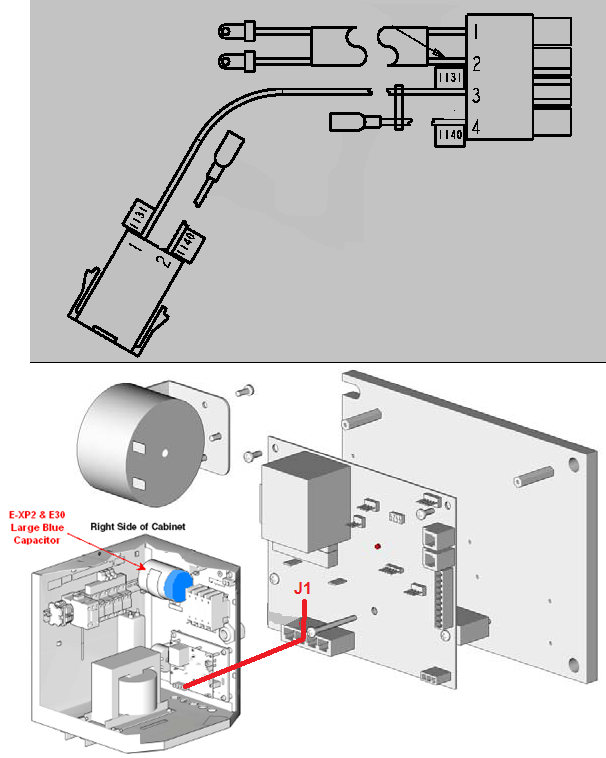
- Remove the Reactor from power source and wait 15 minutes to allow the capacitor to drain the stored energy through the motor circuit.
- Locate the large blue capacitor in the lower cabinet, upper right hand corner.
- Perform a general inspection of the capacitor for shape distortion, cracks, or leakage.
- Short across the two terminal leads with an insulated handle screwdriver to verify the capacitor is fully discharged. Remove the plug from the motor control board J1 connector.
- Set the ohm test meter to a high range of at least 1K ohm. Connect the meter leads black to (-) and red to (+). The meter reading should start at 0 ohms, then move upscale 10K to 20K ohms as the battery from your test meter confirms the capacitor is able to accept a charge.
- A reading of constant 0 zero, (short) or OL, (open loop) would indicate a bad capacitor