E01 : High Fluid Temperature

To avoid serious injury follow all warnings and instructions in the manual. Wear appropriate personal protective equipment.
Check to see if you really do have a high temperature, by using an external temperature-sensing device. If actual fluid temperature is above 190°F (88°C) you will need to cool the unit down to be able to do any testing. Using your feed pumps to move cool material into the Reactor will speed cooling time.
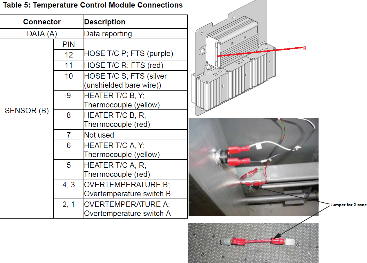
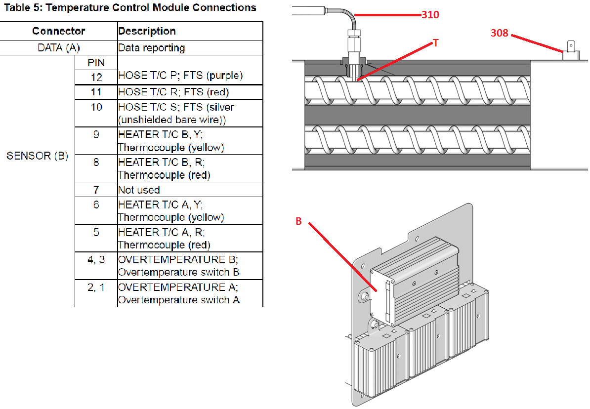
- Check continuity of the over temperature switches by removing the J1/SENSOR B connector from the temperature control module socket. On the plug end check the resistance across pins 1 & 2 and pins 3 & 4 for continuity, (nearly zero ohms).

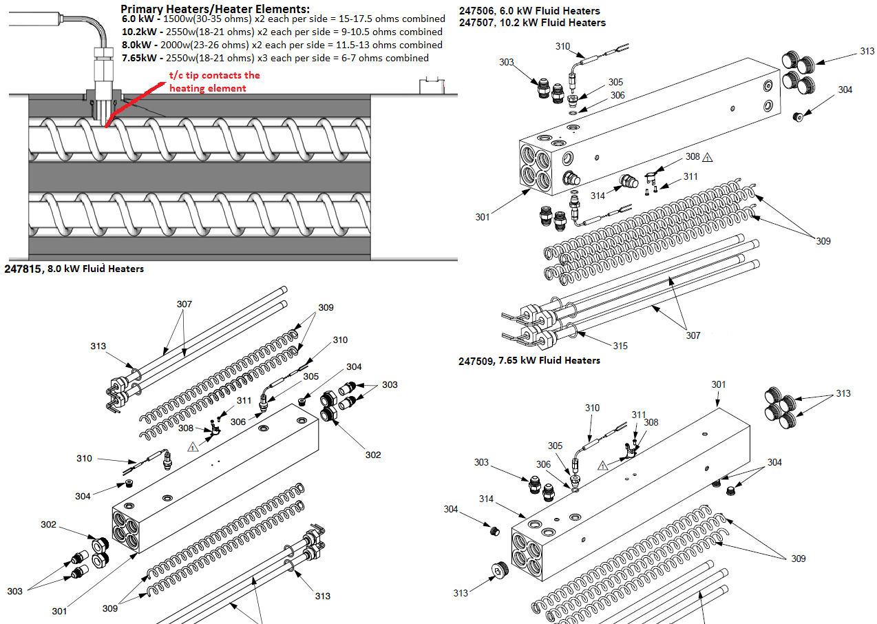
- Check and see if the "A" or the "B" Thermocouple is damaged or not making contact with a working heater element. See section Thermocouple in manual 312066 E-Series, 312063 H-Series, 313540 H-VR-Series.
- Exchange zone module with another one. Turn zone on and check for error. If error moves to another zone, replace the faulty module. (When there is a high current error, the LED on that zone's module will turn red while the error is displayed.
- Check and see if the heater module (BLUE) is turning off when the unit hits the setpoint temperature
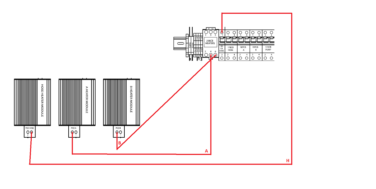
- For "A" heater test points T4 on 238CR & T2 on POD A connector.
- For "B" heater test points T6 on 238 CR & T2 on POB B connector.
- For HOSE test points T1 on 183 CB HOSE & T1 on POD HOSE connector.
- Set the "A", "B", and HOSE set point 10°F/C below the actual temperature, and turn the heat zones on one at a time. The red light on the display above the zone should be blinking and there should be little to no voltage on the voltmeter.
- Measuring voltage while the red light is blinking would indicate that the output on the heater module has failed. Replace the heater module. Note: all 3 modules are the same and can be swapped for troubleshooting.
- Check connections between the temperature control module and the heater "A" & "B" Thermocouples. Make sure all of the wires are securely connected into connector J1/SENSOR B.
- Check continuity of the "A" & "B" thermocouples by removing the J1/SENSOR B connector from the temperature control module socket. On the plug end check the resistance across pins 5 & 6 = 4 - 6 ohms. Pines 8 & 9 = 4 - 6 ohms. Pins 6 & 9 to chassis ground as "OL" open loop at ambient temperature. °
Causes:
- Faulty connection of either of the "A" & "B" thermocouple to the heater control module
- One of the over temperature switches failed in the "open" position. Open circuit in the over temperature wiring harness, or switch "B" jumper is loose or open on a dual zone heater systems.
- Make sure connector J1/SENSOR B is firmly plugged into the heater control module.
- Check connections between the temperature control module and the heater over temperature switches and the "A" & "B" temperature sensor. Make sure all of the wires are securely connected into connector J1/SENSOR B.
- Check continuity of the over temperature switches and the "A" & "B" Thermocouples by removing the J1/SENSOR B connector from the temperature control module socket. On the plug end check the resistance across pins 1 & 2 = nearly Zero ohms, pins 3 & 4 - nearly Zero ohms. Pins 5 & 6 = 4 - 6 ohms. Pins 8 & 9 = 4 - 6 ohms. Pins 6 & 9 to chassis ground os "OL" open loop at ambient temperature.