E04 : Fluid Temperature Sensor (FTS), or "A" or "B" Thermocouple not Connected.

To avoid serious injury follow all warnings and instructions in the manual. Wear appropriate personal protective equipment.
Checking the "A" and "B" side thermocouple assemblies.
Check the electrical connections at the temperature control module.
- Remove plug J1/SENSOR B (Green 12-pin terminal block) from the temperature control module and make sure all pins are securely connected.
- Pin 5 Thermocouple A - red wire connected.
- Pin 6 Thermocouple A - yellow wire connected.
- Pin 8 Thermocouple B - red wire connected.
- Pin 9 Thermocouple B - yellow wire connected.
- Check the "A" & "B" thermocouples by removing the J1/SENSOR B connector from the temperature control module and check the pins with an ohmmeter.
"A" thermocouple:
- With J1/SENSOR B disconnected measure the resistance across pins 5 & 6. It should measure 4 - 6 Ohms at ambient temperature. If not, replace the "A" thermocouple.
- Measure the resistance between Pin 5 & 6 the thermocouple housing. And then between Pin 6 & the thermocouple housing. It should be "OL" open loop, if not replace the "A" thermocouple.
"B" thermocouple:
- With J1/SENSOR B disconnected measure the resistance across pins 8 & 9. It should measure 4 - 6 Ohms at ambient temperature. If not, replace the "B" thermocouple
- Measure the resistance between Pin 8 & the thermocouple housing. And then between Pin 9 & the thermocouple housing. It should be "OL open loop, if not replace the "B" thermocouple.
Check the electrical connections at the temperature control module.
- Looking at plug J1/SENSOR B on the temperature control module, check and see if pins 10, 11 & 12 are connected properly.
- Pin 12 = purple
- Pin 11 = red
- Pin 10 = silver (unshielded bare wires)
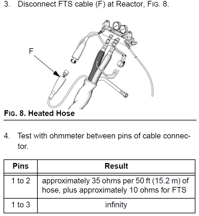
Check the purple wire cable connections between all hose lengths with FTS attached
- Test with an Ohm meter between pins 10 (Silver unshielded bare wire), 11 Red wire, and 12 (Purple wire) of J1/SENSOR B connector disconnected from the Temperature Control Module.
- Pins 11 to 12 approximately 35 ohms per 50' (15.2m) of FTS cable, plus 10 ohms for the FTS.
- Pins 10 to 12 "OL" open loop> 100K ohms.
Check the FTS operation by connecting the FTS directly to the Reactor.
- Locate the FTS.
- Unplug the FTS electrical connection.
- Plug the Reactor end of the connector directly into the FTS electrical connector to see if temperature data appears.
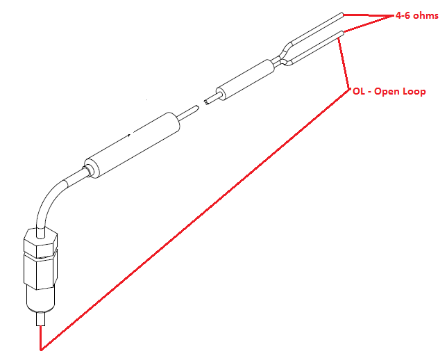
Check the FTS with an ohmmeter.
- Locate the FTS.
- With the main power off, unplug the FTS and measure the pins on the FTS.
- Pins 1 to 2 = 10 Ohms
- Pins 1 to 3 = Infinity "OL" Open Loop
- Pin 3 to FTS ground screw = 0 ohms
- Pin 1 to FTS component "A" (ISO) fitting = Infinity
If the FTS fails any test, replace.
0A (zero amps) on the Hose Zone Display.
- If the FTS is disconnected or the display shows E04, turn the main disconnect off, then on to clear the alarm, and default the machine into manual current hose heat mode. 0A (zero amps) will show in the actual display with the hose zone off.
- When in the target mode of the hose heat zone, amperage can be adjusted from 20A to 45A with the up and down arrow keys.
- To prevent hose overheating, install a thermometer close to the gun end, within the operators view. Insert thermometer through foam insulation cover of the "A" component hose so stem is next to the inner tube. Thermometer reading will be approximately 20F less than the actual fluid temperature. If the thermometer reading exceeds 160F (71C), reduce the current with the down arrow key.
- Thermometer reading should never exceed 160F (71C). Never leave the machine unattended while in a manual current control mode.